
Pressure
Confirm pressure while the filler is cycling. Static pressure at the compressor can hide drop across long pipework, filters, regulators and shared demand.
A pneumatic filler needs more than a compressor with the right pressure on its nameplate. Air quality, flow at the machine, pipework, regulator recovery and simultaneous plant demand all affect cylinder and nozzle movement.
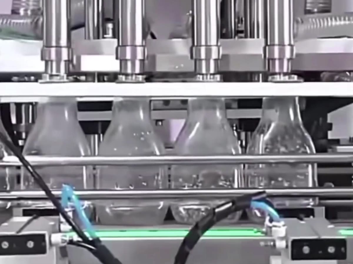
The useful decision is not the label on the machine. It is whether the product, dose, pack, utilities and acceptance method can be controlled together under realistic production conditions.
The Lancing VF documentation gives different values for different configurations. A Craft-series example calls for clean, dry air at 6 bar with approximately 50 litres per minute and an 8 mm connection for heads up to 2.5 litres or 10 mm for a 5-litre configuration. A quoted single-nozzle 100–1000 ml semi-automatic piston filler states approximately 0.4–0.6 MPa. These are examples, not a universal requirement for every machine.
Confirm pressure while the filler is cycling. Static pressure at the compressor can hide drop across long pipework, filters, regulators and shared demand.
The receiver and pipework must recover between strokes and support any simultaneous nozzle, gate or conveyor actuators.
Water, oil or contamination can damage pneumatic components and compromise a production environment. Use the air-quality requirement stated for the supplied machine and process.
| Check | Evidence required | Why it matters |
|---|---|---|
| Available pressure | Dynamic reading at the proposed machine point during normal factory demand. | Low pressure can slow or incomplete actuator movement. |
| Available flow | Compressor, receiver and branch capacity against the quoted machine demand. | Pressure may collapse during repeated cycles even when the static reading looks adequate. |
| Pipe and connector size | Branch length, bore, fittings and the machine connection stated in the manual. | Small or restrictive lines create pressure loss and slow recovery. |
| Treatment | Filter, dryer, drain and any process-specific air-quality controls. | Condensate and contamination reduce reliability and may be unacceptable near product. |
| Isolation and exhaust | Accessible isolation, lock-off method and safe pressure release. | Maintenance and changeover require a controlled zero-energy state. |
Cycle the main piston, nozzle lift, bottle gates and any other pneumatic movements together at the intended rate. Observe regulator pressure, movement repeatability, end cushioning, noise and heat. A machine can appear satisfactory when operated one movement at a time but become unstable during the combined sequence.
Related pages: semi-automatic fillers, installation planning and maintenance guidance.
These answers define the evidence normally needed before Lancing can confirm a machine configuration.
No. Six bar is a published example for certain VF configurations. Use the pressure and flow stated for the exact quoted machine and verify them at the machine connection.
The branch may be restrictive, the receiver may be too small, plant demand may be high, or a regulator/filter may not pass the required flow.
Yes. Condensate and contamination can affect valves, cylinders and controls. The supplied machine and production process should define the required air treatment.
Yes. Site acceptance is the appropriate point to confirm dynamic pressure, combined actuator operation, isolation, leaks and recovery under real factory demand.
Send the proposed air pressure, branch size, compressor information and machine configuration so Lancing can identify any utility checks before installation.