
Line speed
Output should be calculated from the slowest station, not just the filler head count.
An automatic filling line is more than the filler. It needs coordinated product feed, container handling, filling control, capping, labelling, coding, inspection and discharge so every station can keep pace.
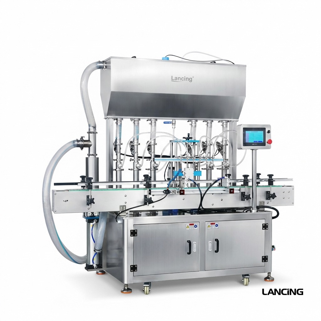
Automatic volumetric fillers are usually specified when output, repeatability and line consistency matter more than manual flexibility. The filler must be planned with the whole packaging process so bottlenecks are removed before installation.
These checks help Lancing UK narrow the correct filling method, machine format and line layout before quotation.
Output should be calculated from the slowest station, not just the filler head count.
Infeed, indexing, gating and conveyor control must hold the container accurately during fill.
Capping, labelling, coding and sealing should be matched to the filler output.
The line needs safe cleaning access, maintenance space and operator visibility.
There is rarely one universal filler for every product. The shortlist should compare the practical filling routes against real production conditions.
For production filling of liquids and pastes where measured volumetric delivery is needed.
For repeatable bottle handling and consistent presentation to the filling heads.
For projects where the filling machine needs to run with closing and decoration equipment.
| Best-fit products | Production liquids, sauces, creams, oils, detergents, viscous products |
| Machine routes | Inline piston, servo piston, pump-based and multi-station packaging lines |
| Important checks | Output target, line bottlenecks, infeed/outfeed, utilities, cleaning and commissioning |
| Typical next step | Provide production target, container drawings/photos and current line layout |
Use these pages to compare product groups, machine types and automation routes.
Automatic filling usually makes sense when production volume, consistency, labour reduction or downstream integration justify a conveyor-based system.
No. Capping, labelling, infeed and outfeed can become bottlenecks, so the full line should be specified together.
Yes. Lancing UK can assist with filling, capping, labelling, coding, conveyors and integration planning.
Send your product, fill volume, container, throughput target and any downstream equipment needed. Lancing UK will narrow the most practical filling route before quotation.
An automatic filler multiplies a tested dosing cycle across several heads and coordinates it with container movement. The final output is therefore a line calculation, not simply the number of nozzles multiplied by a catalogue speed.
| Parameter | Published first-party reference | Project verification |
|---|---|---|
| Head count | 4 filling heads | Confirm head count from the tested dose cycle and required sustained line rate. |
| Volume modules | 5–100, 10–300, 50–500, 100–1000, 500–3000 or 1000–5000 ml | Select the cylinder module for the actual format range; do not assume one module covers every dose. |
| Published accuracy | ≤ ±1% reference | Validate product, temperature, speed, nozzle, feed and head-specific results. |
| Machine features | HMI, sensors, bottle detection, chain conveyor, anti-drip nozzles and stainless contact parts | Confirm recipe, container indexing, cleaning, product-contact materials and control interfaces. |
| Source | Lancing automatic volumetric filling machine | Final configuration and output are project-specific. |
Each head needs a consistent supply path, calibrated setting and clear nozzle. Sampling only combined output can hide a restricted valve, worn tube or head-specific offset. Retain data by head.
Bottles must arrive at repeatable pitch and remain stable during nozzle entry and discharge. Gating, star wheels, screws or servo indexing are selected from the pack and required rate.
Level control, transfer pumps, heated or mixed vessels and return paths must sustain the demand of all heads. Product supply should be tested during a continuous run, not only a short batch.
For the wider automatic machinery catalogue use Automatic Filling Machines UK; this page concentrates on the volumetric dosing stage and its line controls.
These answers explain the checks that normally need to be completed before a machine configuration can be confirmed.
Head count is derived from the required sustained output and the proven fill cycle, then checked against conveyor indexing, product supply, capper and labeller capacity. More heads do not correct a downstream bottleneck.
Sample and identify each head separately, record the individual results and compare head-to-head variation. Repeat after a normal stop, refill and recipe recall.
Verify stored values, user access, head corrections, nozzle motion, conveyor timing and the controlled restart sequence for each approved product and pack format.
Accessible guides and nozzles, repeatable settings, clearly identified change parts, recipe control, tool reduction and a documented verification sequence all matter.
No. Operators still replenish product and components, perform checks, respond to faults, clean, change formats and manage rejects. Automation changes the work rather than eliminating it.
Send the proven or estimated fill cycle, pack formats and rates of every connected machine for a sustained line-output calculation.
An automatic volumetric filler does not operate in isolation. The useful production result is the rate of accepted finished packs through the complete fill, cap, label and discharge sequence, including normal short stops and controlled restarts.
| Line state | Required behaviour | Evidence to retain |
|---|---|---|
| Ready and running | All permissives satisfied, product supply stable and containers released at the agreed pitch. | Recipe, speed, head results, container flow and accepted finished-pack count. |
| Starved upstream | The filler waits without losing recipe, misfiring a nozzle or creating partially processed containers. | Stop reason, retained containers, restart sequence and first accepted fills. |
| Blocked downstream | Container release and filling stop safely before accumulation causes contact, spillage or incorrect indexing. | Sensor state, queue position, fault message and recovery without duplicate filling. |
| No container / incorrect position | No product is discharged unless the correct container is confirmed at the fill station. | No-container-no-fill test and response to tilted, missing or incorrectly spaced packs. |
| Low product or supply fault | The process warns or stops before starvation creates unacceptable fills. | Defined low level or pressure point, final accepted container and restart after replenishment. |
| Downstream machine fault | Capper, labeller, coder or inspection fault is propagated through the agreed line interlock. | Cause, line reaction, pack disposition and controlled recovery. |
| Planned pause and restart | Product, containers and closures remain controlled and the first resumed packs are checked. | Pause duration, product condition, restart sample and any required purge or rejection rule. |
Record scheduled run time, operating time, planned and unplanned stops, rejected packs and accepted output. The filler's instantaneous cycle can support line design, but the sustained result is constrained by container supply, indexing, product replenishment, closure presentation, labelling, inspection and discharge. Use the filling-line OEE calculator to keep availability, performance and quality losses separate.
Keep each sampled fill tied to the filling head and sequence. Verify head balance at normal speed, after a product top-up and after a routine pause before relying on the combined average.
Document the electrical or control signal, normal state, timeout and safe response for each connected machine. A line description such as “ready” or “fault” is incomplete unless both machines interpret the state consistently.
Define what happens to containers in the filler, capper, labeller and conveyor during every stop. Mark rework, purge and reject rules so an uncertain pack cannot re-enter the accepted flow unnoticed.
This page covers automatic volumetric dosing and its line interfaces. For the wider Lancing automatic-machine range, use Automatic Filling Machines UK. Within this site, use line integration, fill-cap-label systems and acceptance testing to define the complete scope.
Send the product, container, closure, label, coding and inspection requirements with the expected run pattern so Lancing can define interfaces and acceptance evidence before quotation.
Automatic filling performance should be measured as accepted finished packs over elapsed time, including the states that occur in normal production.
Filler cycle rate counts the dosing movement, while sellable line output is limited by container infeed, indexing, product replenishment, capping, labelling, coding, rejects, planned stops and restart recovery. A fast filler can wait for another station or produce packs that need rework. Acceptance should therefore measure conforming finished packs over a defined elapsed run.
The capacity calculator helps separate theoretical cycle rate from practical output.
An automatic-line trial should include normal steady running, empty start, product replenishment, container starvation, downstream blockage, planned stop, restart, recipe or format change and recovery from a routine fault where relevant. These states expose control handshakes, accumulation needs and first-fill behaviour that a short continuous demonstration cannot show.
Check each filling head as a separate data series under the same product, feed and speed conditions. Compare its average, spread, restart behaviour and cut-off with the other heads, then investigate mechanical or process differences before applying a blanket correction. A combined line average can look acceptable while one head repeatedly underfills or overfills.
The multi-head balancing guide gives a practical order of checks.
Confirm how many containers can queue without becoming unstable, how the filler reacts to upstream starvation and downstream blockage, and whether filled open containers can wait safely before capping. Accumulation should protect the process rather than simply store more packs. Container shape, product movement, headspace, conveyor control and the restart sequence all affect the answer.
Review the complete sequence in the line integration guide.
Browse automatic-line questions · Balance filling heads · Control restart fills · Plan line interfaces
Send the line sequence, product, containers, closure route and target accepted output so Lancing can assess the complete production cycle.
Plan the filler, conveyor, controls and downstream equipment as one production system.
Choose by accepted line output, product feed, dose range, bottle handling and downstream capacity rather than by head count alone.
A volumetric filling line can contain bottles that were dosed before the most recent adjustment but have not yet reached inspection. Stops and accumulation change that population. Include this delay in the control design rather than assuming the next measured pack represents the latest recipe.
Automatic correction should be inhibited whenever the controller cannot rely on the relevant measurement, operating state or pack attribution. Examples to resolve in the design include stale data, recipe mismatch, unprimed restart and uncertain head identity. Agree the exact behaviour with the equipment suppliers; stopping the entire line and disabling correction are separate decisions.
The feedback specification guide explains how to record those decisions. Use controlled restart checks before restoring normal production and request a review of the actual control interface before assuming it is available.