
Viscosity
The piston size, stroke, speed and product supply should match the thickness and temperature of the product.
Piston filling machines are one of the main volumetric routes for repeatable filling of liquids, sauces, creams, gels, honey, oils and other viscous products. Lancing UK helps specify the filler around the product and container, not just the headline fill size.
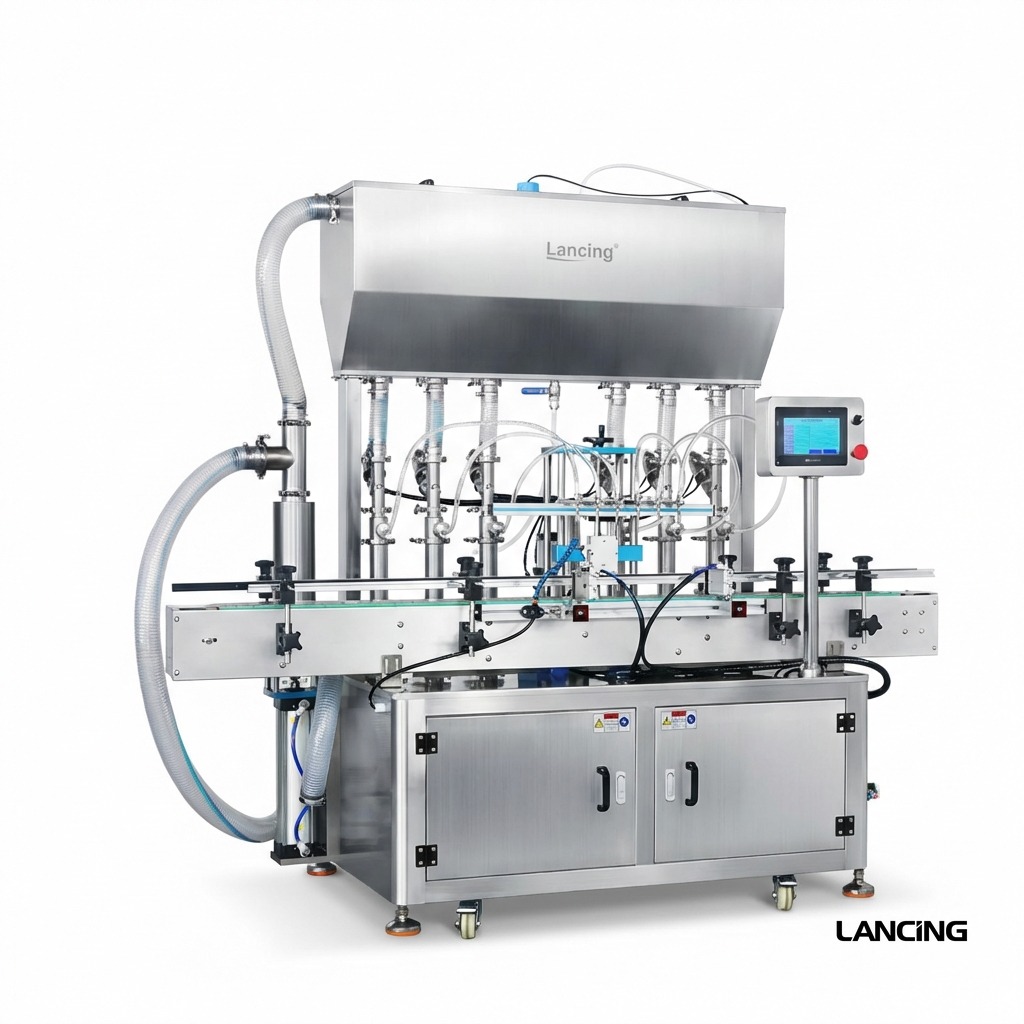
A piston filler draws product into a cylinder and pushes a measured volume through the filling nozzle. That makes it a practical route for products that need repeatable dosing and controlled product movement.
These checks improve the match between the product, filling method and production layout before quotation.
The piston size, stroke, speed and product supply should match the thickness and temperature of the product.
Seeds, herbs, fruit pieces or abrasive particles can influence valve, seal and nozzle choice.
Cylinder sizing should cover the full range of bottle, jar or container volumes expected in production.
Anti-drip, suck-back or shut-off nozzle design affects cleanliness and repeatability.
The strongest enquiry usually compares two or three realistic machine routes against the real production conditions.
Good for smaller batches, operator-fed containers and flexible production where changeover matters.
Designed for conveyor-fed production, higher output, bottle indexing and downstream equipment.
Considered when recipe control, speed adjustment, repeatability and line integration are important.
| Best-fit products | Sauces, honey, creams, gels, oils, lubricants, shampoo, detergent, lotions and viscous food products. |
| Key advantages | Measured displacement, repeatable fill control and suitability for a wide viscosity range. |
| Watch-outs | Particles, aggressive chemicals, product temperature, cleaning access and seal compatibility. |
| Quote information | Product sample details, fill range, container opening, target output and cleaning requirements. |
Better production details allow Lancing UK to narrow the filler route quickly and avoid unsuitable catalogue-style recommendations.
Viscosity, particles, temperature, foam, shear sensitivity, hygiene and cleaning expectations.
Bottle, jar or container dimensions, neck opening, fill range and closure type.
Target output, available footprint, utilities, operator level and future expansion plans.
Use these related pages to compare machine types, product behaviour and the information needed before quotation.
It fills a measured volume by drawing product into a cylinder and discharging it into the container through a nozzle.
No. They are often used for viscous products, but they can also fill many flowing liquids when a positive displacement route is appropriate.
Some piston fillers can handle particles, but the valve, nozzle, seals and product path must be checked against the actual particle size and product behaviour.
Yes. Piston filling can be supplied as a semi-automatic machine or integrated into automatic filling, capping, labelling and coding lines.
Send your product, fill volume, container, throughput target and any downstream equipment needed. Lancing UK will narrow the most practical filling route before quotation.
A piston filler uses positive displacement, but the measured volume is only one part of the result. The cylinder must fill completely, valves must change direction cleanly and the nozzle must release the product without adding drip, air or uncontrolled tailing.
Select a module that covers the required dose range without forcing every format to the extreme end of the stroke. Product-contact materials and seal design must suit the formulation and cleaning method.
The effective stroke sets the displaced volume. Mechanical or servo adjustment must be repeatable and protected from unintended movement. Recipe values should be checked after maintenance or format change.
The inlet/outlet valve controls product direction. Clearances and port geometry must pass the product without blockage, cutting inclusions or trapping material that makes cleaning difficult.
Nozzle bore and shut-off affect discharge pressure, stringing and drip. Suck-back can improve cut-off, but it should be tuned with the product and fill speed rather than maximised.
| Lancing reference | Cylinder / fill options | Published performance | Engineering condition |
|---|---|---|---|
| LU-GY1C single-head pneumatic filler | 5–100, 10–300, 50–500, 100–1000, 500–3000 or 1000–5000 ml optional modules | 10–20 bottles/min; published filling accuracy ≤ ±0.5% | Reference includes a 10 mm nozzle, 0.4–0.6 MPa air and the stated machine setup. The actual product and dose require confirmation. |
| LUDTHSP2 compact automatic filler | 5–100 ml through to 1000–5000 ml module options | 2 heads, customisable to 4; approximately 10–30 bottles/min; published accuracy ≤ ±1% | Speed depends on dose and bottle size. Viscosity, feed, nozzle and conveyor indexing are project variables. |
| Four-head automatic piston filler | 5–100 ml through to 1000–5000 ml module options | 4 heads; published accuracy ≤ ±1% reference; 0.4–0.7 MPa typical air | HMI, sensors, anti-drip nozzles and product supply must be set for the actual container and formulation. |
Run enough consecutive samples to see the distribution rather than a single successful fill. Record each head separately, then repeat after a normal stop and product refill. If all samples remain tightly grouped but miss the target, calibration is the first issue. If the spread grows during the run, inspect supply, air, temperature, valve filling, leaks and nozzle behaviour before accepting the configuration.
These answers explain the checks that normally need to be completed before a machine configuration can be confirmed.
No. A larger cylinder gives more maximum displacement but can reduce useful adjustment resolution for small doses. The cylinder should be selected around the working range rather than only the largest container.
Possible causes include a starved inlet, leaks, excessive draw speed, product aeration, poor hopper level, cavitation or a valve that does not fill the cylinder consistently.
Use the real maximum particle size and concentration. Observe valve passage, seal contact, nozzle clearance, product damage, segregation and whether particles settle between cycles.
A pump route may be stronger for continuous product feed, certain shear-sensitive products, difficult inclusions or cleaning requirements. The actual product path and control method should be compared in a trial.
After drain-down and cleaning, check seals, valve orientation, cylinder or stroke setting, nozzle, recipe and head-specific adjustment, then run controlled samples before releasing production.
Many multi-head systems allow head-specific correction. Each head should be sampled and recorded separately so one restricted valve or nozzle is not hidden by the overall average.
Provide the product at its real operating temperature plus the full dose range so the cylinder, valve, seals and nozzle can be selected as one system.
A piston volumetric filling machine is repeatable only when the parts and settings that define the measured chamber and discharge path are controlled. The production record should identify the cylinder, usable stroke, valve, seals, nozzle and product condition for every approved format.
| Configuration item | Record for each SKU | Reason it matters |
|---|---|---|
| Cylinder and piston assembly | Part or size reference, seal set and approved minimum/maximum operating range | A cylinder selected too far from the required dose can reduce useful adjustment and make small changes harder to reproduce. |
| Stroke or recipe | Mechanical setting or controlled recipe value, target dose and calibration date | The stroke defines displaced volume, but the delivered result still depends on complete draw, valve transfer and clean discharge. |
| Valve and product path | Valve type, port orientation, hose or pipe arrangement and any product-feed setting | Restriction, air entry, incomplete valve movement or product starvation can create variation that is not corrected by changing stroke alone. |
| Nozzle and cut-off | Nozzle bore, height, insertion or diving movement, shut-off and suck-back settings | The same measured dose can produce different pack cleanliness, foam, stringing and residual product depending on discharge conditions. |
| Product condition | Temperature, batch condition, particle description, hopper level and time since mixing | Viscosity and particle distribution can change draw, pressure, cut-off and the result seen at each head. |
Published Lancing references show the range of possible configurations, but they are not a substitute for a product trial. The LU-GT1 single-head piston filler lists 5–20 bottles/min, several cylinder options from 10–100 ml to 1000–5000 ml and ≤ ±0.5% for that reference. The LU-YT4T-4Y four-nozzle line configuration lists 20–35 bottles/min, options from 5–100 ml to 1000–5000 ml and ≤ ±1% for its published configuration. Different machine architecture, product, dose and test conditions mean those figures cannot be used as a direct head-count scaling calculation.
Record every sampled fill against its nozzle or head and sequence number. Calculate each head's mean, minimum, maximum and range before combining results. Pooling all fills can hide one head that is consistently high, low or unstable.
Sample at start-up, after a normal pause, after product replenishment and near the end of the planned run. Transition fills show valve priming, air entry and product-supply effects that steady-state samples may miss.
After cylinder, seal, valve or nozzle work, verify assembly, zero or home position, stroke setting, leakage and a short accepted sample. The previous recipe is evidence only when the same controlled parts and product condition have been restored.
A stable single-head result supports a later automatic piston filler or multi-head filling line. If tubing isolation, very small liquid contact volume or rapid wetted-part change is more important, compare the piston and peristaltic routes. If continuous pump behaviour is needed, review the piston and gear-pump comparison.
Provide representative product, the full fill range, container neck details and expected batch pattern so the cylinder, valve and nozzle trial can be planned around production conditions.
The cylinder establishes the displacement range, the valve controls suction and discharge direction, and the nozzle controls product presentation at the container. A strong result requires all three to suit the product and operating cycle.
Prove both the smallest and largest required fills rather than assuming one cylinder will perform equally well across its theoretical extremes.
Select cylinder sizeCheck refill, closure, particles, retained product, cleaning access and seal condition.
Compare valve routesIdentify which cylinders, seals, nozzles, guides, gates and recipes are common or dedicated to each SKU.
Plan change partsA piston filler is a connected system: cylinder, stroke, inlet, valve, nozzle, feed and drive must work with the same product condition.
An oversized piston cylinder can force a small dose into a very short working stroke. That may reduce adjustment resolution and make valve clearance, trapped air, retained product and cut-off behaviour a larger share of the delivered quantity. The smallest required fill should therefore be tested with the intended cylinder, valve and nozzle rather than assumed from the maximum cylinder capacity.
Use the cylinder size guide to define the working window.
A restrictive or unsuitable valve can slow cylinder refill, create pressure changes, damage particles, trap air or prevent complete discharge. The piston may repeat its movement while the product path fails to repeat the same condition. Valve passage, seal compatibility, switching timing, cleanability and the largest normal particle should be assessed together with the cylinder and nozzle.
The piston filler valve guide sets out the evidence to collect.
Repeatability can change when viscosity, temperature, aeration, particle loading, hopper level, suction speed, valve timing, seals, nozzle settings or cleaning residue differ from the approved condition. Re-entering the same numerical recipe does not guarantee the same process. A controlled changeover should verify product preparation, prime state and the first accepted fills before normal production resumes.
For diagnosis, separate consistent bias from random spread and head-specific variation.
Compare servo and pneumatic piston filling when recipe control, automatic adjustment, motion profiling, line synchronisation or a wide product and dose range may justify more controlled movement. Pneumatic filling can remain practical for simpler semi-automatic work where the product, utilities and operator cycle are stable. The decision should be based on the real changeover and production task, not on drive technology alone.
See the pneumatic versus servo guide for the main trade-offs.
Diagnose changing fill quantities · Balance multiple filling heads · Check cylinder and stroke · Check valve selection
Send the dose range, product condition, particles, container and output target so the cylinder, valve, nozzle and drive can be assessed together.
Review the cylinder, valve, nozzle, product feed and test evidence as one dosing system.
Draw and discharge time change with viscosity, dose, valves, nozzle and feed. Container indexing and downstream machinery then set the accepted rate. Review what affects volumetric filling speed.
Group individual results by head and operating state, then compare the process centre with the spread. See accuracy versus repeatability.
Temperature can change recharge, discharge, density and cut-off. The temperature guide explains the evidence to retain.
Include the hopper or hose, cylinder, piston seal, valve, fittings and nozzle. Use the product-contact materials checklist.
Published model data is useful only when the cylinder module, product feed, valve, nozzle, container and test method are kept in view.