
Foam and splash
Thin liquids can splash or foam at speed, so nozzle depth and filling profile need review.
Liquid filling machinery should be selected around viscosity, foam, fill volume, container stability, nozzle cut-off and whether the project needs a standalone machine or a complete production line.
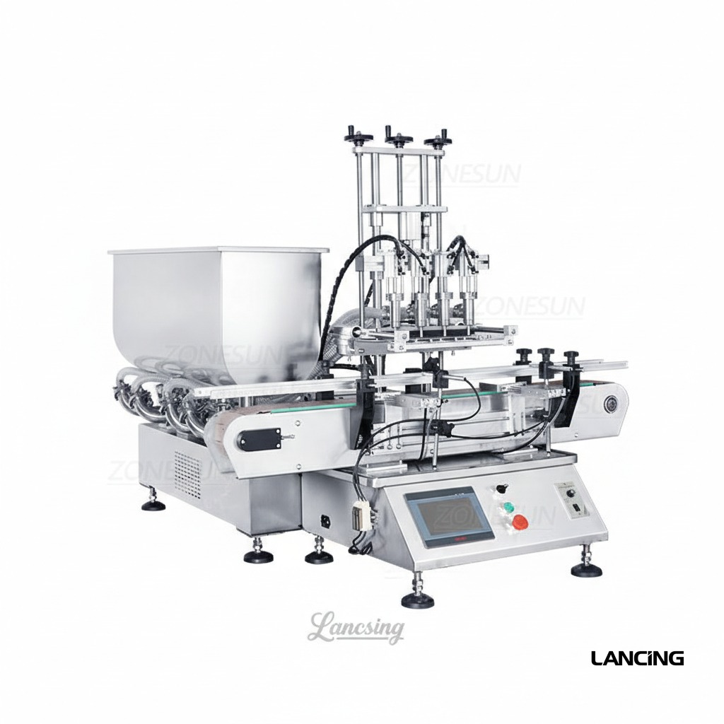
Free-flowing liquids, oils, detergents and low-viscosity products can look simple, but splash, foam, drip control and bottle handling often decide the right filler format.
These checks improve the match between the product, filling method and production layout before quotation.
Thin liquids can splash or foam at speed, so nozzle depth and filling profile need review.
Cleaning method, tubing, seals and stainless contact parts should match the product and sector.
Tall or light bottles may need guides, indexing and support before the nozzle layout is chosen.
Bottles per minute, number of heads and downstream equipment decide whether semi-auto or automatic is realistic.
The strongest enquiry usually compares two or three realistic machine routes against the real production conditions.
Often suitable for free-flowing liquids where product delivery and tubing route can be controlled.
Useful where measured displacement and stronger repeatability are needed across a defined fill range.
For production lines where conveyors, gating, capping and labelling must run together.
| Best-fit products | Oils, detergents, sanitiser, cleaning fluids, low-viscosity food products and flowing liquids. |
| Common container types | Plastic bottles, glass bottles, jerry cans, jars, tubs and open containers depending on handling. |
| Important checks | Foaming, splash, chemical compatibility, drip control, fill tolerance, bottle neck and closure route. |
| Next step | Send bottle photos, fill volume, target bottles per minute and product details. |
Better production details allow Lancing UK to narrow the filler route quickly and avoid unsuitable catalogue-style recommendations.
Viscosity, particles, temperature, foam, shear sensitivity, hygiene and cleaning expectations.
Bottle, jar or container dimensions, neck opening, fill range and closure type.
Target output, available footprint, utilities, operator level and future expansion plans.
Use these related pages to compare machine types, product behaviour and the information needed before quotation.
Liquid filling machines can be specified for oils, detergents, sanitiser, cleaners, low-viscosity foods and many flowing products when the filling principle is matched to the product.
Often yes. Thin liquids may need splash control, anti-drip shut-off, diving nozzles or bottom-up filling depending on the container and speed.
Yes. Liquid fillers can be supplied as semi-automatic stations or as automatic inline machines with conveyors, capping and labelling.
The key details are product type, viscosity, fill volume, bottle size, cap style, target output and whether the filler must integrate with other equipment.
Send your product, fill volume, container, throughput target and any downstream equipment needed. Lancing UK will narrow the most practical filling route before quotation.
A low-viscosity liquid does not automatically need the same filler as every other thin liquid. Conductivity, volatility, tubing compatibility, air content, container opening and cleaning can change the strongest route.
| Liquid route | Best reason to compare it | Evidence needed | Specialist ownership |
|---|---|---|---|
| Piston liquid filling | Positive displacement and controlled cut-off across flowing to moderately viscous liquids | Viscosity range, seal compatibility, cylinder module, valve filling and nozzle behaviour | Piston filling engineering guide |
| Peristaltic filling | Liquid remains in replaceable tubing, supporting clean product-path changes and small doses | Tube material and bore, product compatibility, wear, maximum flow and calibration | Piston versus peristaltic guide |
| Gear, diaphragm or rotor pump | Continuous pump delivery for a suitable liquid or viscous product | Pump curve, shear, solids, pressure, cleanability and the dosing control used | Liquid Fillers UK catalogue |
| Flowmeter | Direct flow measurement for a compatible liquid and meter technology | Conductivity or meter principle, air bubbles, solids, flow window and cleaning | Specialist liquid-filling review |
| Time-pressure | Simple timed delivery where supply pressure and product behaviour can be held stable | Head pressure, valve timing, temperature, viscosity and supply-level variation | Verify drift over the full production batch |
| Reference configuration | Published dose / flow | Published speed / accuracy | Important condition |
|---|---|---|---|
| LUDTPP4F compact four-head peristaltic filler | Recommended 10–500 ml at 110 V or 10–1000 ml at 220 V; up to approximately 4000 ml/min per nozzle on water | Approximately 30–50 bottles/min; published accuracy ≤ ±1% on water | Four independent heads, 0.3–0.4 MPa air and model-specific tubing. Different liquids require a new trial. |
| LUSVPP80C servo peristaltic filler | Maximum published flow 2.4 L/min × 4 channels | Published 10–20 bottles/min at 100 ml | Performance is dose- and product-dependent; the product contacts the tubing and the tube is part of the calibrated system. |
| LU-GY1C piston reference | Alternative modules from 5–100 to 1000–5000 ml | 10–20 bottles/min; published accuracy ≤ ±0.5% | Piston route for compatible liquids and pastes; result depends on selected cylinder, product and setup. |
Measure the effect of nozzle bore, discharge speed, fall distance, headspace and bottom-up motion. A slower initial stage followed by faster bulk fill may control foam without making the whole cycle unnecessarily slow.
Confirm wetted materials, seals, tubing, hoses and cleaning chemicals. Corrosive, solvent or high-purity liquids can require a specialist product path that is more important than the headline filling principle.
Check the first controlled fills after priming, a normal production pause and a product-supply refill. Air, drain-back and changing head pressure often appear at these transitions rather than during a short steady run.
These answers explain the checks that normally need to be completed before a machine configuration can be confirmed.
It is useful where the liquid can pass through suitable tubing, product contact should be limited to the tube and quick product-path changeover is valuable. Tube compatibility, wear, flow and dose range must still be tested.
Foam can be created by high discharge velocity, air in the product, excessive fall distance, turbulent return flow or the formulation itself. Speed profiling, a larger nozzle or bottom-up filling may help after a product trial.
Viscosity, surface tension, tube condition, product supply and dose affect the result. A figure measured on water is evidence for that stated condition, not a guarantee for oil, shampoo, solvent or another liquid.
For suitable clean flowing liquids, especially continuous or larger fills, direct measured flow may be appropriate. Meter type, conductivity, air, solids, viscosity and cleaning determine suitability.
Record tube material, bore, length, pump setting and installation method. Prime the tube, inspect for wear or flattening and recalibrate after replacement.
Its primary purpose is usually foam and splash control. It can support more stable filling by keeping the nozzle close to the liquid surface, but motion, timing and cut-off must be coordinated with the dose.
Send the liquid, safety data where relevant, temperature range, container and required dose so the product path and measurement method can be compared.
Two products described as liquids can require different volumetric filling routes. A useful specification records what the liquid does during supply, acceleration, discharge, cut-off and restart, then compares piston, peristaltic, flowmeter or time-pressure filling against those conditions.
| Observed liquid behaviour | Data to record | Routes and trial focus |
|---|---|---|
| Water-like and non-foaming | Density, temperature, target dose, container neck and required cycle | Compare suitable pump, peristaltic, piston or flowmeter routes; verify cut-off and supply stability rather than assuming low viscosity guarantees a clean fill. |
| Foaming or surfactant-rich | Foam rise, collapse time, fill height, fall distance and acceptable settling time | Compare reduced velocity, staged flow and bottom-up or diving nozzles; measure accepted finished packs rather than only pump flow. |
| Volatile, solvent-bearing or chemically aggressive | Safety data, vapour risk, material compatibility, ventilation and cleaning controls | Engineering and site-risk review must precede selection. Do not infer suitability from a generic liquid-filler description. |
| High-purity or contact-sensitive | Permitted wetted materials, tubing or seal requirements, cleaning method and change frequency | A peristaltic route may reduce product contact to suitable tubing; verify tubing life, occlusion, calibration and disposal requirements. |
| Temperature-sensitive or viscosity-changing | Cold, nominal and warm filling temperatures with flow observations | Test the proposed method across the permitted temperature range because draw, pressure, flowmeter response and cut-off can change. |
| Contains entrained air or arrives under variable pressure | Supply pressure, pump state, deaeration, tank level and restart behaviour | Stabilise the feed condition and compare repeated results before adjusting the dose control. Supply variation can look like a calibration fault. |
Record the condition of the product vessel, transfer pump, hose or pipework and filler inlet before each test. Sample the first fills after priming, a routine stop, product replenishment and a longer pause. Note air bubbles, foam, delayed product arrival, pressure changes and any temporary difference between heads. A method that is stable only after several rejected containers may need a controlled priming or restart routine.
Define the normal product level, transfer method, inlet pressure and any recirculation or agitation. Repeat the trial near the low operating level so starvation or pressure loss is identified before production.
Record nozzle bore, height, fill speed profile, shut-off or suck-back and the state of the container after filling. Check neck, shoulder and label area, not only net quantity.
Keep individual results with head and sequence identity, plus product temperature and restart status. Separate systematic bias from random spread and from a single-head difference.
This site covers volumetric method selection and integration. For the wider Lancing liquid-filler catalogue and specialist liquid-machine routes, use Liquid Fillers UK. Within this site, compare piston filling, peristaltic filling and the volumetric filling buyer guide without creating duplicate machine pages.
Include the normal temperature, supply arrangement, container, fill range and restart pattern so Lancing can select the methods that deserve a controlled trial.
Thin and medium-viscosity liquids can suit several dosing methods. Compare how each route responds to temperature, pressure, aeration, minimum dose, valve response and cleaning instead of selecting from a generic accuracy figure.
Use this route when comparing cylinder modules with electronic flow measurement across a broad container range.
Compare methodsUse this route for small liquid doses or compact product paths where supply pressure and timed flow can be controlled.
Compare methodsPneumatic configurations also require a verified compressed-air supply at the machine.
Liquid filling becomes repeatable when the dosing method receives the product in a controlled condition and the nozzle presents it consistently to the pack.
Product-feed pressure matters because it can change how consistently a cylinder or pump refills, whether air is drawn into the path and how quickly the machine is ready for the next cycle. A volumetric mechanism may repeat its setting while an unstable supply creates different inlet conditions. The trial should include the expected high and low feed states.
Use the product-feed guide to compare hopper, tank and pumped supply arrangements.
Entrained air occupies space inside the measured volume but does not represent the same quantity of liquid after the bubbles collapse or escape. It can enter through mixing, pumping, splashing, a low hopper level or suction leaks. The result may appear as random variation, foam, delayed level change or a different weight for the same apparent volume.
The first containers after a restart can differ because product pressure, temperature, prime state, valve position, nozzle wetting and air content may not yet match steady production. A stopped line can also allow particles to settle or product to drain back. Start-up and restart fills should be included in the acceptance method rather than treated as an operator surprise.
The start-up and restart guide provides a practical test sequence.
Test the approved viscosity range at the real production temperatures and preparation states, including any mixing, recirculation or dwell time that changes flow. Observe refill time, air entrainment, nozzle cut-off, foam and actual line output at each boundary. A single room-temperature sample cannot prove a process that normally runs across materially different conditions.
Record the liquid condition beside every result so the accepted settings remain meaningful.
Browse liquid and process questions · Stabilise product feed · Test restart fills · Review nozzle behaviour
Provide the formulation range, temperature, feed method, container and required output so Lancing can test the liquid route at its operating boundaries.
Compare the measurement principle under the real viscosity, temperature, foam and product-supply conditions.
Temperature can change viscosity, density, foam and cut-off. Record the temperature at the filling point and review the product-temperature guide.
Use net product mass divided by verified density under the agreed condition. The weight-to-volume guide and calculator covers tare, density and records.
A liquid may contact hoses, seals, valve seats and nozzles that differ from the frame material. Use the wetted-material guide.
Foam, splash, bottle neck, nozzle movement, pump or piston recharge and downstream handling can all become the bottleneck. See the speed guide.
Use the reference configuration to frame a product trial, then confirm the wetted path, dose, bottle, nozzle and accepted line output.